
The servo object is now fully initialized and ready to control the servo. In the setup function, we attach digital pin number 9 to the servo object. The second variable is the rotation value that will be sent to the servo motor. The first one is used to store the values retrieved from the sensor/potentiometer. Then, a servo object is created that will be used to control the servo motor.

Next, we define two pins: digital pin 9 for the servo motor and analog pin A0 for the rotary angle sensor (or potentiometer). In order to use this library, we have to include its header file. Luckily, the Arduino IDE has already a built-in servo library.

The pin in the middle is the signal pin which corresponds to the sensor’s SIG pin and must be connected to an analog input pin (e.g. If a potentiometer is used instead of the rotary angle sensor: Typically, the outer pins of the potentiometer must be connected to the power supply (GND and 5V pin of the Arduino). Finally, the sensor’s SIG pin must be connected to one of the Arduino’s analog input pins. The pin in the middle is the VCC pin, which must be connected to breadboard (same column as the other two pins). The sensor’s left pin is the ground which must be connected to one of the Arduino’s GND pins.

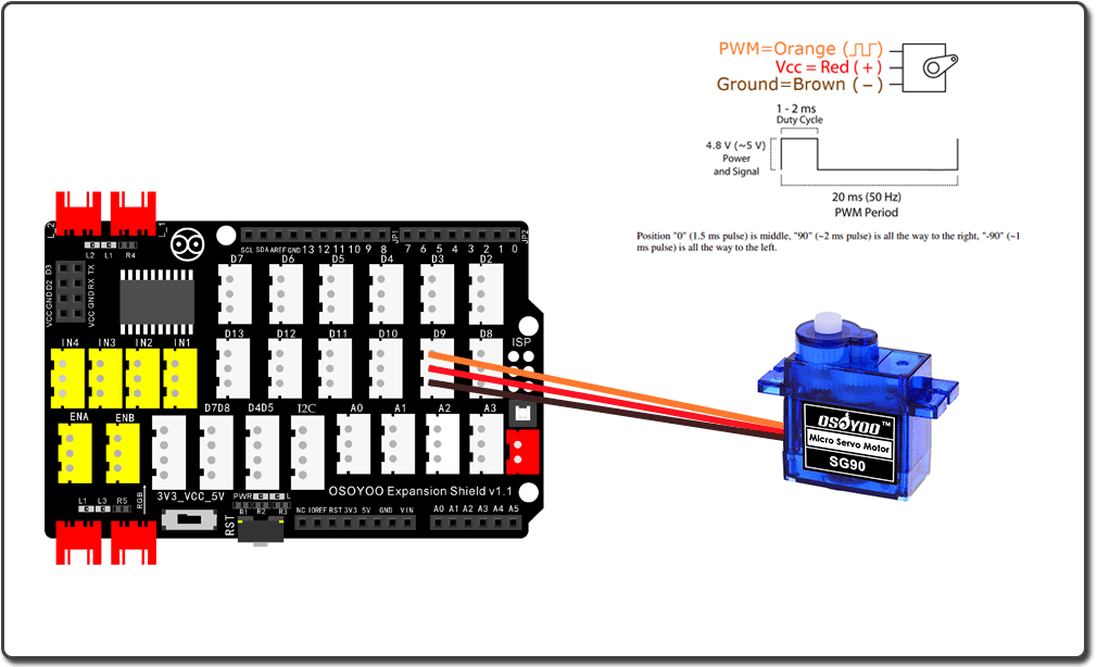
In this tutorial, digital pin 9 of the Arduino is used for this task and, therefore, wired to the SG90’s yellow pin.įollowing, we have to wire the rotary angle sensor to the Arduino. In order to control the SG90 servo, PWM signals (Pulse Width Modulation) must be sent through the yellow wire. Next, the brown wire of the SG90 must be connected to one of the Arduino’s GND pins. Then, the servo’s red wire is connected to the breadboard (same column as previous pin). The Arduino’s 5V pin is connected to a breadboard. Since the Arduino Uno has only one 5V pin, we use a breadboard to split the 5V signal. Both, the servo and the rotary angle sensor need a voltage supply. In order to control the SG90, a rotary angle sensor is used.įirst, we connect the SG90 servo motor to the Arduino Uno.
2 servo motor arduino code how to#
Pin layout: A scheme that shows how to wire the micro servo motor SG90 to an Arduino Uno. – Potentiometer (in alternative to the rotary angle sensor) Therefore, it can be simply replaced by almost any potentiometer, since it is used here only for convenience reasons. This module is nothing more than a conventional potentiometer combined with a knob. In order to control the motor, a so-called rotary angle sensor module is used. In this tutorial, it is shown how to control the SG90 servo motor. Moreover, is is very small and lightweight (Weight: 9g Dimension: 22.2 x 11.8 x 31 mm). The SG90 is such a servo motor that can rotate approximately 180°. Both can be used to control the servo motor. In the background is a rotary angle sensor module and a potentiometer. Nonetheless, servo motors are very useful if a projects requires a motor with a precise control and awareness of its current position. However, the disadvantage of these servos is that the rotation range is limited (e.g. In particular, a command can be sent to the servo so that the servo’s shaft rotates to a specific position. As a result, servo motors can be controlled very precisely. Among these four things, the potentiometer acts as a position sensor. Typically, servo motors are a combination of four things: a conventional DC motor, a set of gearings, a potentiometer, and a control circuit.


 0 kommentar(er)
